


Shell and tube heat exchangers dominate industrial heat transfer applications, representing the majority of exchangers installed in refineries and petrochemical processing facilities. Their widespread adoption can be attributed to robust mechanical construction, adaptability across a broad range of operating conditions, and design practices that have been refined over decades under internationally recognized standards. These units are indispensable across numerous sectors—from chemical manufacturing and petroleum refining to power generation, HVAC systems, and food processing.
This guide offers a detailed examination of the principal components that constitute a heat exchanger components, their respective functions, and the design frameworks that govern their specification and fabrication.
What Is a Shell and Tube Heat Exchanger?
At its most fundamental level, a shell and tube heat exchanger comprises a cylindrical outer vessel—the shell—within which a bundle of tubes is housed. One fluid stream travels through the interior of the tubes, commonly referred to as the tube side, while a second fluid flows over the exterior of the tubes within the shell enclosure, designated as the shell side. Heat transfer occurs across the tube wall, with the two fluids remaining physically separated throughout the process.
This design offers considerable versatility: the exchanger can accommodate fluids in liquid, gaseous, or multiphase states, function under elevated temperatures and pressures, and be engineered to meet specific process requirements.
Major Components of a Shell and Tube Heat Exchanger
The shell and tube exchanger can be organized into four principal assemblies: the front header, rear header, tube bundle, and shell. Within these broader categories, numerous individual elements work in concert to enable effective and dependable heat transfer.
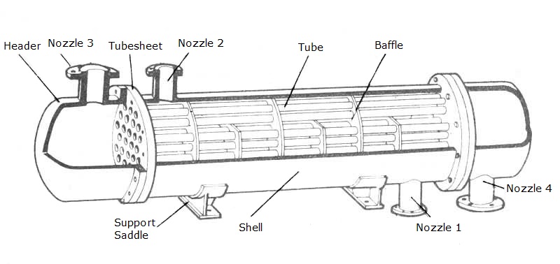
1. Shell
The shell serves as the outermost cylindrical pressure vessel, housing the tube bundle and directing the shell-side fluid across the tubes. Shell construction typically employs either seamless pipe or rolled-and-welded plate, with flanged connections at each end.
Design features:
- Shell diameters span from approximately 150 mm (6 inches) for compact units to over 3,000 mm (120 inches) for large-scale refinery applications
- Carbon steel represents the most economical and widely used shell material
- The shell incorporates flanged nozzles that enable the shell-side fluid to enter and exit
- Nozzle placement is carefully considered to promote even flow distribution and maximize heat transfer performance
2. Tube Bundle
The tube bundle constitutes the functional core of the heat exchanger, containing the tubes, tube sheets, baffles, tie rods, and spacers that collectively form the heat transfer surface.
Tubes
Tubes are the primary heat transfer elements within the exchanger. One fluid passes through the tubes while exchanging thermal energy with the fluid on the shell side.
- Common tube outside diameters include 5/8 inch, 3/4 inch, and 1 inch
- Tube lengths typically fall between 2.4 m (8 ft) and 7.3 m (24 ft)
- Tube options include seamless or welded constructions
- Tubes may be straight or configured as U-shaped bends
- Surface modifications—such as fins or internal rifling—can be applied to enhance heat transfer rates
Tubes are secured at each end into tube sheets, with the tube-to-tubesheet joint achieved through hydraulic or roller expansion, often supplemented by strength or seal welding.
Tube Sheets
Tube sheets are thick, flat plates precision-drilled with an array of holes that accommodate the tube ends. These plates perform dual structural and functional roles: they anchor the tubes in position and establish a pressure boundary that separates the tube-side fluid from the shell-side fluid.
- Tube sheets are typically fabricated from materials compatible with the tubes
- Hole patterns—specified by tube pitch—are selected to balance heat transfer efficiency against pressure drop considerations
- The tube sheet is exposed to both fluid streams simultaneously, necessitating corrosion-resistant material selection or adequate corrosion allowances
Baffles
Baffles are plates installed perpendicular to the tube axis within the shell, serving two essential purposes:
- Mechanical support: Baffles restrain the tubes against vibration and deflection
- Flow management: Baffles redirect the shell-side fluid in a cross-flow pattern across the tube bundle, inducing turbulence that substantially improves heat transfer coefficients
The single segmental baffle with a 25% cut represents the most commonly employed configuration. Baffles also contribute to fouling mitigation by maintaining fluid velocity across the heat transfer surfaces.
Tie Rods and Spacers
Tie rods and spacers secure the baffle assembly and maintain consistent spacing between successive baffles. The tie rods are anchored to the end baffle at one extremity and to the tube sheet at the other. The required number of tie rods and spacers is determined by the shell diameter and the total number of baffles in the bundle.
3. Front Header (Stationary Header)
The front header—also designated as the stationary header—provides the entry point for tube-side fluid into the exchanger. Common front header configurations are identified by TEMA designations including A, B, C, D, N, and Y. Header selection is influenced by considerations such as flow arrangement, pressure rating, cost constraints, and maintenance accessibility.
4. Rear Header
The rear header serves as the exit point for tube-side fluid or, in multi-pass configurations, as the return location where fluid is redirected to the front header. Common rear header types include L, M, and N designations. In fixed tubesheet designs where thermal expansion is a concern, expansion joints or bellows may be incorporated to accommodate differential movement.
5. Nozzles
Nozzles are flanged connections installed on the shell and heads that provide the entry and exit pathways for both fluid streams. A typical exchanger features four nozzles:
- Shell-side fluid inlet
- Shell-side fluid outlet
- Tube-side fluid inlet
- Tube-side fluid outlet
6. Bonnets (End Caps)
Bonnets—also referred to as heads or end caps—are fitted at each extremity of the tube bundle. Their function is to direct tube-side fluid into and out of the tubes. Removable bonnet designs facilitate routine maintenance and tube bundle cleaning.
7. Gaskets and Seals
Gaskets are critical sealing components positioned between tube sheets and the shell, as well as between the shell and bonnets. These seals—typically fabricated from materials such as rubber or PTFE that resist elevated temperatures and chemical attack—prevent fluid leakage and maintain the integrity and safety of the exchanger.
8. Supplementary Components
Additional elements that may be incorporated into a shell and tube heat exchanger include:
- Impingement plates: Shield tubes from direct fluid impingement at inlet nozzles
- Pass partition plates: Divide tube-side flow into multiple passes
- Longitudinal baffles: Guide shell-side flow along the exchanger length
- Sealing strips: Minimize fluid bypass around the tube bundle
- Expansion joints: Accommodate differential thermal expansion in fixed tubesheet designs
Types of Shell and Tube Heat Exchangers
Shell and tube heat exchangers are categorized according to their construction features—principally the stationary head configuration, flow arrangement, and rear-end closure design. The three principal types are:
| Type | Key Features | Best Suited For |
|---|---|---|
| Fixed Tubesheet | Simplest design, tube sheets welded to shell, no relative movement | Minimal differential thermal expansion, limited shell-side fouling |
| U-Tube | Tubes bent into U-shape, single tubesheet, accommodates expansion | Applications where thermal expansion is significant; cleaning less critical |
| Floating Head | One tubesheet fixed, other floats to allow axial movement | High thermal differentials, mechanical cleaning required on both sides |
Fixed Tubesheet
Economical, no internal moving parts, but tube bundle not removable. Ideal for clean services and small temperature differences.
U-Tube
Natural expansion accommodation, lower cost due to single tubesheet. Inner tube cleaning is challenging.
Floating Head
Allows full mechanical cleaning, handles large temperature swings. More complex and costly than fixed type.
Design Standards and Classifications
Shell and tube heat exchangers are designed and fabricated in accordance with established international standards:
TEMA (Tubular Exchanger Manufacturers Association): The TEMA Standards are the definitive reference for shell and tube heat exchanger construction. The current Tenth Edition (2019) recognizes three service classifications:
- Class R – Refinery and petroleum service (most rigorous)
- Class B – Chemical process service
- Class C – General commercial service (least demanding)
ASME (American Society of Mechanical Engineers): The ASME Boiler and Pressure Vessel Code (Section VIII) provides broader coverage of pressure vessels, encompassing shell and tube heat exchangers.
TEMA employs a three-letter designation system to specify exchanger configuration: the first letter denotes the front head type, the second indicates the shell type, and the third identifies the rear head type. For example, a BEM designation indicates a bonnet front head, single-pass shell, and fixed tubesheet rear head.
Quality Replacement Parts for Shell & Tube Heat Exchangers
At Shanghai T.S. Industrial Co., Ltd., we specialize in supplying a wide range of replacement parts and components for shell and tube heat exchangers across various industries. Our product portfolio covers the vast majority of components discussed in this guide—including tubes, tube sheets, baffles, tie rods, spacers, front and rear headers, bonnets, gaskets, sealing elements, impingement plates, and expansion joints. All supplied components are available in configurations that meet TEMA, ASME, and other international standards, ensuring reliable compatibility with your existing systems.
Whether you require standard spare parts for routine maintenance or custom-engineered solutions for specific operating conditions, we are committed to delivering quality, reliability, and competitive lead times. Our team works closely with clients to understand their process requirements and provides technical support to guide material selection, dimensional accuracy, and performance optimization.
For inquiries, quotes, or technical consultation on heat exchanger components, please contact us today. Let us be your trusted partner in keeping your heat transfer systems running efficiently and safely.