

Functions and Application of Heat Exchanger Baffle
Baffles are critical components in shell and tube heat exchangers, with their design directly influencing shell-side fluid dynamics, thermal efficiency, and mechanical stability. As industrial heat exchange requirements become increasingly demanding, baffle technology has evolved significantly. This comprehensive analysis examines baffle functionality from fundamental principles to advanced engineering applications, supported by performance data and case studies.
Heat Exchanger Baffle Performance Metrics
Modern heat exchanger baffles must balance multiple engineering parameters: heat transfer coefficient, pressure drop, vibration resistance, fouling mitigation, and structural integrity. Optimal baffle design can improve overall exchanger efficiency by 30-50% while reducing operational costs through decreased pumping requirements and extended maintenance intervals.
Heat Exchanger Baffle Functions
Fluid Dynamics Control and Heat Transfer Enhancement
Baffles fundamentally alter shell-side fluid behavior through strategic flow redirection. The primary mechanisms include:
- Boundary Layer Disruption: By forcing repeated directional changes, baffles disrupt laminar boundary layers, transitioning flow from laminar to turbulent regimes. This turbulence significantly enhances convective heat transfer coefficients. Experimental data indicates properly designed baffle arrangements can increase shell-side heat transfer efficiency by 30-50% compared to unbaffled configurations.
- Flow Distribution Optimization: Baffles eliminate "flow short-circuiting" where fluid bypasses the tube bundle through shell-to-bundle gaps. This ensures uniform fluid contact across all heat transfer surfaces, eliminating localized thermal inefficiencies.
- Residence Time Control: Strategic baffle placement regulates fluid velocity and residence time within the exchanger, optimizing the balance between heat transfer and pressure drop.
Structural Support and Vibration Mitigation
Beyond thermal performance, baffles provide essential mechanical functions:
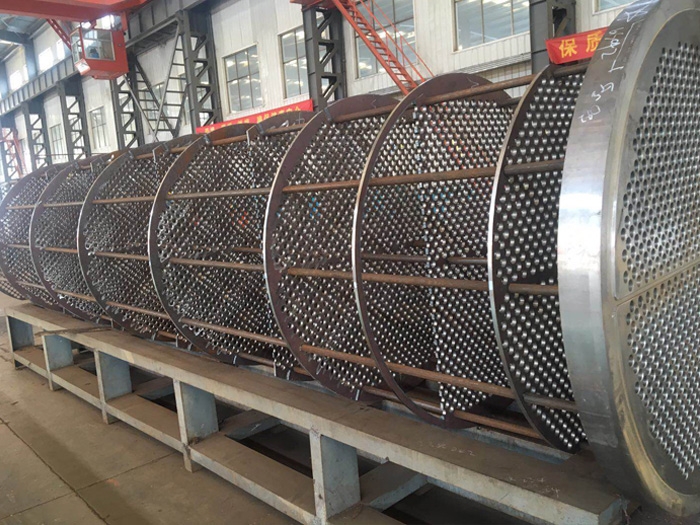
- Tube Bundle Stabilization: Baffle openings maintain precise tube positioning, preventing displacement from fluid-induced forces or thermal expansion. Proper tube support spacing is critical for long-term reliability.
- Flow-Induced Vibration (FIV) Suppression: Under high-velocity or pulsating flow conditions, unsupported tube spans are susceptible to vibration-induced fatigue failure. Baffles increase tube bundle stiffness, reducing vibration amplitudes. For example, reducing baffle spacing from 300mm to 200mm in a chemical processing application decreased tube vibration amplitude from 1.2mm to 0.3mm, eliminating fatigue failure risk.
Pressure Drop Management
The relationship between baffle design and system pressure drop represents a critical engineering trade-off:
Baffle Spacing vs. Performance Characteristics
| Spacing Ratio (Baffle Pitch/Shell ID) | Heat Transfer Coefficient | Pressure Drop | Recommended Applications |
|---|---|---|---|
| 0.2-0.3 | High (115-130%) | Very High (180-220%) | High-viscosity fluids, space-constrained designs |
| 0.4-0.6 | Optimal (100%) | Balanced (100%) | General chemical processing, standard applications |
| 0.7-1.0 | Moderate (80-90%) | Low (60-75%) | Low-pumping power systems, gas processing |
Engineering Insight: Reducing baffle spacing by 50% typically increases pressure drop by approximately 200%, while only improving heat transfer by 25-35%. This nonlinear relationship necessitates careful optimization during design.
Heat Exchanger Baffle Type Selection and Comparison
| Baffle Type | Flow Characteristics | Heat Transfer Efficiency | Pressure Drop | Fouling Resistance | Typical Applications |
|---|---|---|---|---|---|
| Segmental Baffle | Cross-flow, multiple flow reversals | High (100% baseline) | High (100% baseline) | Low | Standard chemical, petroleum processing |
| Disc & Doughnut | Longitudinal flow dominated | Medium (85-90%) | Low (60-70%) | Medium | High viscosity fluids (heavy oil, polymer melts) |
| Helical Baffle | Continuous spiral flow | High (95-105%) | Medium (70-80%) | High | Energy-efficient systems, scaling media |
| EMBaffle® & Grid | Longitudinal flow, minimal obstruction | Medium (80-85%) | Very Low (30-40%) | Very High | Gas processing, low-flow applications |
| Rod Baffle | Longitudinal flow, no dead zones | Medium (85-90%) | Low (50-60%) | High | Vibration-sensitive applications |
Heat Exchanger Baffle Design
Critical Geometric Parameters
- Baffle Cut Percentage (Cut%): The ratio of segment height to shell diameter, typically 20-45%. Lower values (15-25%) increase velocity but create significant dead zones; higher values (35-45%) reduce pressure drop but may compromise heat transfer.
- Baffle Spacing: Optimal spacing ranges from 0.2 to 1.0 times the shell inner diameter. Closer spacing enhances heat transfer and vibration resistance but exponentially increases pressure drop.
- Helix Angle (Helical Baffles): Typically 30-45°, with lower angles providing more flow resistance and higher heat transfer, while higher angles reduce pressure drop.
- Tube-to-Baffle Hole Clearance: Critical for vibration control and thermal performance. Standard clearance is 0.4-0.8mm, with tighter tolerances (0.2-0.4mm) in vibration-prone applications.
Material Selection Guidelines
| Service Environment | Recommended Baffle Material | Key Properties | Application Notes |
|---|---|---|---|
| General Chemical Service | Carbon Steel (SA-516 Gr. 70) | Cost-effective, good mechanical strength | Compatible with most hydrocarbons and aqueous solutions |
| Chloride Service | 316/316L Stainless Steel | Excellent chloride stress corrosion cracking resistance | Cooling water with chloride >200ppm |
| Cryogenic Service | 304/304L Stainless Steel | Good toughness at low temperatures | LNG, air separation units (-196°C to 50°C) |
| High Temperature (>500°C) | 321/347 Stainless Steel | Carbide stabilization for intergranular corrosion resistance | Reformer, cracking furnace applications |
| Severe Corrosion | Duplex 2205 / 6% Mo Austenitic | Pitting and crevice corrosion resistance | Offshore, chemical processing with halides |
Heat Exchanger Baffle Failure Analysis and Design Solutions
Case Study 1: Vibration-Induced Tube Failure
Situation: A refinerys naphtha hydrotreater charge heat exchanger experienced repeated tube failures within three months of commissioning. Inspection revealed 12 tubes with fatigue cracks near the baffle supports.
Root Cause: Excessive baffle spacing (400mm) combined with high shell-side velocity created unsupported tube spans vulnerable to flow-induced vibration. The natural frequency of the tube bundle coincided with vortex shedding frequency, resulting in resonant vibration.
Solution: Implemented reduced baffle spacing (250mm) with a double-segmental configuration to maintain thermal performance while increasing tube support frequency. Additionally, tube-to-baffle hole clearance was reduced from 0.8mm to 0.4mm.
Result: Vibration amplitude decreased from 1.2mm to 0.3mm, eliminating fatigue failures. The exchanger has operated continuously for over five years without further issues.
Case Study 2: Fouling and Efficiency Degradation
Situation: A seawater cooling exchanger at a coastal facility experienced 40% reduction in heat transfer efficiency within six months due to severe biological and particulate fouling in the stagnant zones behind traditional segmental baffles.
Root Cause: Conventional segmental baffles created significant dead zones where suspended solids and marine organisms accumulated, progressively reducing effective heat transfer area.
Solution: Retrofitted with helical baffles providing continuous spiral flow path with minimal stagnation areas. The helical design also incorporated a slightly enlarged tube-to-baffle clearance to allow for easier cleaning.
Result: Fouling accumulation rate decreased by 60%, extending cleaning intervals from six months to two years. Overall thermal performance improved by 15% due to more uniform flow distribution.
Design Verification Checklist
- Confirm baffle spacing prevents tube vibration across all operating conditions
- Verify baffle cut orientation optimizes flow distribution
- Ensure materials compatibility with process fluids and operating temperatures
- Validate pressure drop calculations against system pump capabilities
- Confirm adequate thermal expansion accommodation in baffle design
- Verify manufacturability of selected baffle configuration
Heat Exchanger Baffle Trends
Baffle design continues to evolve with advancements in computational fluid dynamics (CFD), additive manufacturing, and material science. Emerging trends include:
- Hybrid Baffle Designs: Combining features of multiple baffle types to optimize specific performance characteristics
- Additively Manufactured Baffles: Complex internal flow channels and optimized geometries not feasible with traditional manufacturing
- Smart Baffles: Integrated sensors for real-time monitoring of vibration, fouling, and thermal performance
- Advanced Materials: Non-metallic composites offering corrosion resistance, reduced weight, and improved manufacturability
Baffles have evolved from simple flow directors to sophisticated components that balance thermal, mechanical, and operational requirements. Proper baffle selection and design requires comprehensive understanding of fluid dynamics, heat transfer principles, and mechanical integrity considerations.