T-shaped finned tube|U bend low fin tube
T-shaped Finned Tube Introduction:
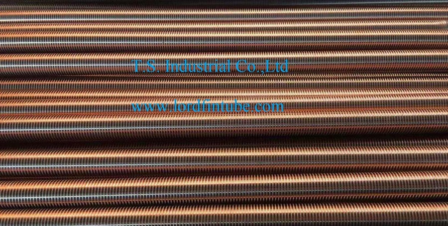
T-shaped finned tubes are highly efficient heat exchange tubes created through the rolling process of a light tube. The tubes structure features spiral annular T-shaped tunnels on its outer surface. When heated, these tunnels generate bubble nuclei that expand rapidly, fill the cavity, and eject through fine cracks, creating a significant flushing force. This action causes lower-temperature liquid to flow into the tunnels, forming continuous boiling. This process results in a heat transfer rate much higher than that of light tubes. This overview delves into the research progress, principles, characteristics, heat transfer mechanisms, and applications of T-shaped finned tubes.
Table of Contents:
1. Introduction
2. Research Progress
3. Principles
4. Characteristics
5. Heat Transfer Mechanisms
6. Applications
7. Development and Application of T-shaped Finned Tube Reboilers
Introduction to T-shaped Finned Tubes:
Invented by the German company Wieland-Werke in 1978, T-shaped finned tubes have been extensively researched for their enhanced heat transfer performance. In China, their applications have expanded into the refining and petrochemical fields, with industrial tests showing that T-shaped finned tube reboilers save over 30% of heat exchange area compared to light tube reboilers, maintaining high efficiency even under production overload conditions.
T-shaped Finned Tubes Research Progress:
T-shaped finned tubes (Gewa-T tubes) are among the four primary boiling enhanced surfaces globally, significantly improving the boiling heat transfer coefficient and critical heat load compared to light tubes. Research has demonstrated that T tubes heat transfer performance is up to five times higher than that of light tubes. However, apart from research by Chongqing University, domestic development has been limited, highlighting the need for further studies.
Principles of T-shaped Finned Tubes:
The rolling process forms a series of spiral annular T-shaped tunnels on the tubes outer surface. When heated, bubble nuclei rapidly expand and eject, creating a flushing force and causing continuous boiling. This process significantly enhances the boiling heat transfer capability compared to light tubes.
Characteristics of T-shaped Finned Tubes:
1. Excellent Heat Transfer Efficiency: In R113 refrigerant, the boiling heat transfer coefficient is 1.6-3.3 times higher than that of light tubes.
2. Lower Temperature Difference Requirement: Unlike conventional tubes, T-shaped finned tubes require only a 2°C-4°C temperature difference for boiling to start, compared to 12°C-15°C for light tubes.
3. High Performance in Various Media: Experiments show significant improvements in boiling heat transfer coefficients in different media.
4. Cost-effective: Cheaper than aluminum porous surface heat transfer tubes.
5. Fouling Resistance: Intense gas-liquid disturbance prevents fouling, ensuring long-term efficiency.
Heat Transfer Mechanisms:
The heat transfer process in T tubes involves several stages:
1. Natural convection heat transfer.
2. Local film evaporation and convection heat transfer.
3. Nucleate boiling heat transfer.
4. Film evaporation heat transfer.
5. Film boiling or burning heat transfer.
Understanding these stages helps explain the enhanced performance and boiling delay phenomena observed in T tubes.
Applications of T-shaped Finned Tubes:
T-shaped finned tubes can be used in heat exchangers, especially where the shell-side medium is clean and free of solid particles and colloids, to improve boiling heat transfer efficiency.
Development and Application of T-shaped Finned Tube Reboilers:
An industrial test stand for T-shaped finned tube reboilers was implemented at Sinopec Changle Branch, replacing a floating-head shell-and-tube reboiler. The new reboiler, with an actual heat transfer area of 90.5 m², exceeded design heat loads and met production requirements, demonstrating the practical advantages of T-shaped finned tubes in industrial applications.