


What Is Included in a Waste Heat Boiler Package?
A waste heat boiler package turns a hot exhaust stream into usable steam or hot water. The package groups every component needed for that duty: one or more heat-transfer bundles, inlet and outlet headers, a steam drum where steam is generated, connecting ductwork, soot blowers, isolation and blowdown valves, instruments, and the supporting structure. The assembly is built into transportable modules in the workshop and delivered to site for final tie-in.
Because the modules are aligned, welded and tested before shipment, site work is limited to foundations, module lifting, final duct and pipe connections, electrical wiring and commissioning. That reduces work at height, shortens the construction window, and allows weld quality to be verified under controlled workshop conditions.
A typical package contains:
- Evaporator heating surface, plus superheater and economiser sections where the duty requires them
- Steam drum, headers and internal fittings
- Interconnecting ductwork and expansion joints between modules
- Soot blowers, steam, acoustic or air operated, for dust-laden gas
- Valves, safety valves, blowdown and sampling lines
- Instrumentation for pressure, temperature, flow and drum level
- Insulated support steelwork, access platforms and ladders
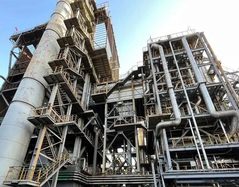
Core Definitions: Packaged Waste Heat Boiler, WHRB Packaged Unit and HRSG Package
- Waste heat boiler package
- A complete heat recovery unit supplied as matched modules, covering pressure parts, ducting, cleaning equipment and instrumentation for one defined exhaust gas duty.
- Packaged waste heat boiler
- The same equipment described by its supply format: assembled and tested in the workshop, then shipped as modules so that only final connections are made on site.
- Waste heat recovery boiler package
- A broader term that also covers the bypass duct, diverter damper, soot blowing system, feedwater controls and auxiliary equipment around the boiler itself.
- HRSG package
- A heat recovery steam generator placed downstream of a gas turbine or reciprocating engine. It is often multi-pressure and is supplied as an integrated HRSG package.
- WHRB packaged unit
- A waste heat recovery boiler built as a packaged unit, usually recovering heat from process furnaces, kilns, smelters or incinerators rather than from a turbine exhaust.
Key Parameters and Units
Four parameters fix most of the geometry and most of the material selection. They only make sense when the measurement basis is stated.
Steam output
Unit: t/h or kg/h. This is the mass flow of steam evaporated from the recovered heat. It is an output of the heat balance, not an independent choice.
Design pressure
Unit: MPa(g) or bar g. Design pressure sets wall thickness, drum class and valve rating. Gauge and absolute pressure must never be mixed within one calculation.
Flue gas inlet temperature
Unit: °C. The gas temperature entering the unit sets the material grade of the hottest section and determines whether a radiant cooling section is needed ahead of the convective bundle.
Heat recovery efficiency
Unit: %. The share of available gas heat that is recovered. The definition must be stated: gas-side enthalpy drop, or heat recovered divided by fuel lower heating value. The two bases give different numbers and cannot be compared directly.
How these parameters interact
A higher gas inlet temperature increases available heat and therefore steam output. Pushing the gas outlet temperature lower increases heating surface and gas-side pressure drop, which raises fan power or turbine back pressure. Higher design pressure increases wall thickness, material cost and module weight, which tightens transport and lifting limits. Steam output, design pressure and gas inlet temperature are therefore linked: changing one without adjusting the other two usually produces an unbuildable or uneconomic unit.
How Heat Recovery and Steam Output Are Calculated
Sizing starts on the gas side, then moves to the steam side.
Where Q is recovered heat in kW, ṁg is gas mass flow in kg/s, cp is gas specific heat in kJ/(kg·K), and Tin and Tout are gas inlet and outlet temperatures in °C.
Where ṁs is steam mass flow in kg/h, Q is in kW, hs is outlet steam enthalpy in kJ/kg, and hfw is feedwater enthalpy in kJ/kg. For saturated steam, hs is taken at the drum pressure.
Heating surface follows from the heat transfer equation: A = Q / (U × ΔTlm), where A is surface area in m², U is the overall heat transfer coefficient in W/(m²·K), and ΔTlm is the log mean temperature difference in K. A fouling allowance is normally added for dust-laden gas, and it has a significant effect on the calculated area.
Configuration Comparison
| Comparison dimension | Packaged waste heat boiler | Field-erected HRSG package | Notes |
|---|---|---|---|
| Workshop completion | Assembled into modules; bundles, headers and pipework pre-fitted | Shipped as loose components and individual tube sections | Module content depends on manufacturer capability |
| Site welding | Limited to inter-module joints | Extensive; bundles, ducting and piping welded on site | Site welding affects the non-destructive examination scope |
| Transport limits | Module size limited by road, barge and crane capacity | Fewer limits; large components can be split | Shipping route survey should be done before design freeze |
| Construction schedule | Usually shorter; workshop and civil work run in parallel | Longer; site sequence is largely serial | Schedule also depends on site readiness |
| Quality control conditions | Stable workshop welding and testing environment | Site welding exposed to weather and access constraints | Both must follow the project specification |
| Future modification | Less flexible; bounded by module size and structure | More room for adding surface on site | Margins should be reserved at the design stage |
| Typical fit | Medium and small units, retrofits, constrained sites | Large units, very high gas flows, oversized components | Final choice follows the actual project constraints |
| Comparison dimension | Water-tube | Fire-tube |
|---|---|---|
| Gas path | Gas passes outside the tubes; water inside | Gas passes inside the tubes; water outside |
| Pressure suitability | Suits medium and high pressure; typical range 0.7 to 10 MPa(g) | Suits low pressure; typical range up to about 2 MPa(g) |
| Dust-laden gas | Tube pitch can be widened and soot blowers fitted | Internal fouling is harder to remove |
| Footprint and weight | Larger and heavier for the same output | More compact |
| Thermal response | Lower water volume, faster response | Higher water volume, greater thermal inertia |
Design Trade-offs and Selection Trade-offs
No single configuration optimises every objective at once. Four trade-offs decide most designs.
Heat transfer area against gas-side pressure drop
Adding surface lowers the gas outlet temperature and raises recovery, but it also increases pressure drop. Higher pressure drop means more fan power, or higher back pressure on an upstream turbine, and that can cancel part of the recovered energy.
Approach point temperature against recovery rate
Approach point is the difference between the gas temperature leaving a section and the saturation temperature of the water or steam inside it. A tighter approach point increases recovery, but it requires disproportionately more surface and a larger casing.
Material grade against acid dew point
Dropping the outlet temperature below the acid dew point forces the use of corrosion-resistant alloys or protective coatings. The cost of the material upgrade has to be weighed against the value of the additional heat recovered.
Module size against transport and lifting capability
Larger modules reduce site welding but are constrained by the shipping route, barge capacity and the crane available at site. These limits must be confirmed before detailed design is frozen, not after.
Technical Parameters
| Parameter | Unit | Typical range | Remark |
|---|---|---|---|
| Steam output | t/h | 1 to 100 | Set by the gas-side heat balance |
| Design pressure | MPa(g) | 0.7 to 10 | Gauge pressure; state the basis clearly |
| Steam temperature | °C | Saturation to 540 | Superheat depends on process demand |
| Flue gas inlet temperature | °C | 300 to 1,200 | Above this range a radiant section is normally required |
| Flue gas flow | Nm³/h | 5,000 to 500,000 | Referenced to a stated base condition |
| Heat recovery efficiency | % | 60 to 90 | Definition of the basis must be stated |
| Gas-side pressure drop | kPa | 0.5 to 3 | Affects fan power or turbine back pressure |
| Feedwater temperature | °C | 20 to 150 | Depends on the deaerator arrangement |
Materials and Standards
Material selection follows the gas-side temperature, composition and dust loading.
| Component | Typical material | Selection basis |
|---|---|---|
| Evaporator and superheater tubes | Carbon steel or low-alloy steel; alloy or stainless grades in the hottest and most corrosive sections | Metal temperature and acid dew point |
| Drum and headers | Carbon steel or low-alloy steel plate and forgings | Design pressure and temperature |
| Ducting and casing | Carbon steel with internal insulation; corrosion-resistant grade where dew point risk exists | Gas composition and insulation detail |
| Soot blowers | Stainless or heat-resistant alloy | Gas temperature and cleaning medium |
| Insulation | Mineral wool or calcium silicate, with cladding | Operating temperature and surface loss target |
Applicable design and fabrication standards: according to project specification; the applicable standard is to be confirmed for each unit. Most projects reference a local boiler code or a recognised pressure equipment code, and the edition named in the contract is the governing one. No standard or certification should be assumed to apply to a specific unit until it is confirmed in writing.
Applications
- Iron and steel: converter, reheating furnace and coke oven off-gas, where gas is hot, intermittent and often dusty.
- Cement and lime: kiln and clinker cooler exhaust, where dust loading drives the cleaning system design.
- Glass: furnace flue gas at high temperature, often requiring a radiant cooling section.
- Chemical and petrochemical: process furnace flue gas and exothermic reactor off-gas.
- Refining and hydrogen production: reformer and process heater exhaust.
- Power generation: gas turbine and reciprocating engine exhaust, handled as an HRSG package.
- Waste to energy: incinerator flue gas with aggressive composition and high dust load.
- Non-ferrous metallurgy: smelting and roasting furnace off-gas.
- Sulphuric acid and acid gas plants: process gas cooling with strict dew point control.
- Pulp, paper and ceramics: recovery boiler and kiln exhaust streams.
Selection Method for a Waste Heat Recovery Boiler Package
- Fix the gas-side data: mass flow, inlet temperature, composition, dust loading, dew point, allowable pressure drop and load profile.
- Fix the steam-side demand: pressure, temperature, flow, feedwater temperature, water quality and whether the duty is continuous or cyclic.
- Run the heat balance and state the efficiency basis explicitly.
- Compare water-tube and fire-tube arrangements at comparable pressure drop.
- Set material grades from the dew point and corrosion risk, not from habit.
- Match the module split to the shipping route and the crane capacity at site.
- Define soot blowing, bypass arrangement, safety valves and instrumentation scope.
- Confirm the performance guarantee and the acceptance test scope before order placement.
Quality Checks and Inspection
Inspection scope is set by the project specification, but the following checks are common on packaged units:
- Material certification and traceability for pressure parts
- Dimensional inspection of modules against approved drawings
- Weld visual inspection and non-destructive examination of pressure welds
- Hydrostatic or pneumatic pressure test of the pressure envelope
- Drum internals and header bore inspection
- Soot blower function test and rotation check
- Instrument loop check and control valve stroke test
- Performance test where the contract requires one
Packing and Shipping
Modules are shipped with the pressure envelope sealed and the internals protected. Because the largest module usually governs the transport study, packing decisions are made early and in parallel with design.
- Pressure openings closed with blind plates; tube ends capped
- Internal surfaces protected against moisture during sea transit
- Modules braced and skidded on the transport frame, with lifting points marked
- Loose items crated and itemised against the packing list
- Shipping marks, centre of gravity and lifting diagrams included in the documentation
- Module dimensions and weights confirmed against the route survey before dispatch
Frequently Asked Questions
What is a waste heat boiler package?
A waste heat boiler package is a factory-assembled heat recovery unit that converts hot exhaust gas into steam or hot water. It typically ships as transportable modules containing pressure parts, headers, drums, tube bundles, soot blowers, ducting and instrumentation, so site work is limited to foundations, final tie-ins and commissioning.
What is the difference between a packaged waste heat boiler and a field-erected HRSG package?
A packaged waste heat boiler is assembled into modules in the workshop and needs less site welding. A field-erected HRSG package is shipped as loose components and assembled on site. Packaged units shorten the construction schedule, but module size is limited by transport and lifting capability.
How is steam output calculated for a waste heat recovery boiler package?
First calculate the gas-side heat release, Q = gas mass flow × specific heat × (gas inlet temperature − gas outlet temperature). Then divide by the enthalpy rise of the steam: steam mass flow = Q × 3600 / (steam enthalpy − feedwater enthalpy). Unit consistency must be checked at every step.
Which flue gas parameters define the design?
Gas mass flow, inlet temperature, composition, dust loading, dew point and allowable pressure drop define the gas side. Steam pressure, steam temperature, feedwater temperature and load profile define the water and steam side.
Why is the gas outlet temperature not lowered further?
Because acid dew point corrosion, dust deposition and fouling risk increase as the metal temperature falls. A lower outlet temperature also requires more heat-transfer surface, a larger casing and higher gas-side pressure drop.
What are the main trade-offs in selecting a packaged waste heat boiler?
Heat-transfer area against gas-side pressure drop, approach point temperature against recovery efficiency, material grade against acid dew point, and module dimensions against transport and crane limits.
What heat recovery efficiency can a WHRB packaged unit reach?
Efficiency depends on gas inlet temperature, gas outlet temperature and the steam conditions. Typical range is 60% to 90%. Final values must be confirmed against project specifications, engineer approval and manufacturer data.
Which inspections are performed before shipment?
Typical checks include material certification, dimensional inspection, weld visual and non-destructive examination, hydrostatic or pneumatic pressure test, soot blower function test, and a performance test where the contract requires one. The exact scope is confirmed by project specification.
Request a Quote for a Waste Heat Boiler Package
Sizing a waste heat recovery boiler package starts with the exhaust gas data. Send the gas flow, inlet temperature, composition, dust loading and the required steam pressure and temperature, and the engineering team will review the arrangement, the module split and the applicable inspection scope. Lordfintube also manufactures the pressure parts and manifold headers used in these units.
Share your gas and steam conditions to receive a technical review and commercial proposal.