


Lordfintube--High frequency welding serrated finned tube
High-frequency welding serrated finned tubes are helically wound fin tubes where a notched (serrated) steel strip is continuously resistance-welded to a base tube at 200–450 kHz, producing a metallurgical bond at the fin-to-tube interface. The serrations break the gas-side boundary layer, raising the apparent heat transfer coefficient by roughly 8–20% compared with solid fin tubes of the same footprint, while accepting a measurable pressure-drop penalty. They are specified primarily for heat recovery steam generators (HRSGs), economizers, fired heaters, and waste heat recovery equipment where gas-side thermal resistance dominates.
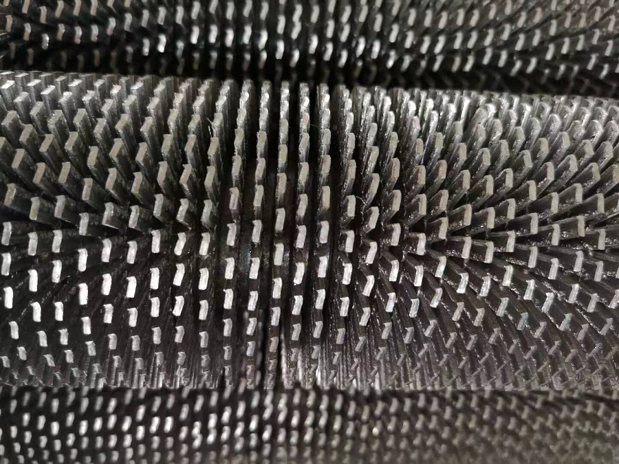
What are High-frequency welding serrated finned tubes?
A high-frequency welding serrated finned tube is a composite heat-transfer element: a base tube (typically carbon steel, alloy steel, or stainless steel) with a continuous serrated fin strip welded to its outer surface by high-frequency electric resistance welding (HFERW). “Serrated” means the fin edge is notched — cut into segments — along its height.
The welding process itself is the defining manufacturing step. The fin strip is helically wound around a rotating base tube while high-frequency current (commonly in the 200–450 kHz range) is applied through contacts, heating the fin-to-tube interface to forging temperature under pressure. The result is a metallurgical bond, not a mechanical fit. This matters because mechanically attached fins lose contact under thermal cycling, creating a contact resistance that degrades heat transfer over time. A welded bond does not.
Serrated fins differ from solid (plain) fins only in geometry. After the strip is fed, it is notched at regular intervals before welding. That notch pattern is the entire reason serrated tubes exist as a separate product category.
Why does serration matter? Heat transfer vs. pressure drop
Serration improves the heat transfer coefficient by disrupting the boundary layer on the gas side, but it does so at a measurable flow resistance cost. This is the central trade-off in selection.
Experimental comparisons between serrated and solid helical finned tubes under the same tube and fin dimensions consistently show a thermal performance advantage for serrated fins, but not a free one. A study comparing segment-height ratios reported approximately 8.2% higher thermal performance for serrated fins, with a flow performance decrease of about 7.5%. The same body of work indicates that the serrated advantage is larger at low gas flow rates — roughly 30% higher apparent heat transfer coefficient at low flow versus about 18% at high flow.
| Parameter | Serrated fin | Solid fin | Practical implication |
|---|---|---|---|
| Apparent heat transfer coefficient | Higher (≈8–20% in cited comparisons) | Lower | Serrated is favored when gas-side resistance dominates |
| Gas-side pressure drop | Higher | Lower | Fan or ID fan power must be sized accordingly |
| Fin efficiency correction | ≈3–7% | ≈12–33% | Serrated fins retain more effective surface at height |
| Fouling sensitivity | More sensitive — deposits lodge between serrations | Less sensitive | Serrated is best with clean or low-fouling fuels |
| Weight (same envelope, similar surface) | ≈9% lighter in cited comparison | Baseline | Relevant for structural support and shipping |
The engineering conclusion is not “serrated is better.” It is: serrated finned tubes are appropriate when the gas stream is clean enough that deposits will not bridge the serration gaps, and when the additional pressure drop can be absorbed by the system fan. Solid fins remain the safer choice for heavily fouling service or when pressure drop is tightly constrained.
What materials are used, and which combination fits which service?
Material selection for high-frequency welding serrated finned tubes follows a temperature-and-corrosion logic, not a preference ranking. The base tube and fin material must be compatible to avoid galvanic effects and differential expansion problems at the weld.
| Combination | Typical service temperature | Suitable environment | Common applications |
|---|---|---|---|
| Carbon steel tube + carbon steel fin (e.g., SA179/SA210 + SA1008 strip) | < 400°C | Clean flue gas, low-to-medium pressure, non-aggressive | Boiler economizers, petrochemical fired heaters |
| Stainless steel tube + stainless fin (304/316L, or 409 fin) | > 400°C where corrosion present | Sulfur-bearing or mildly acidic flue gas | Waste heat recovery, FGD/SCR downstream sections |
| Alloy steel tube + alloy fin (T11, T22, T91) | High wall temperatures | Ultra-high pressure steam, high-temperature flue gas | Power plant superheaters/reheaters, HRSG high-temperature sections |
| Carbon steel tube + Type 409 stainless fin | Intermediate | Compromise between cost and fin-side oxidation resistance | Mixed-service economizers; a common commercial HFW combination |
Two constraints govern these combinations. First, the fin material must tolerate the metal temperature at the fin tip, which is higher than the base tube wall temperature under gas-side heating. Second, for Cr-Mo steel tubes (T11, T22, T91), ASME standards call for post-weld heat treatment of the base material; however, peer-reviewed analysis of HFW Cr-Mo finned tubes has concluded that the high-frequency resistance welding process itself is reliable without post-weld heat treatment, provided the welding parameters are controlled. This is a point where manufacturer practice and code language can diverge — it should be confirmed against the specific project specification and applicable ASME/PED clause, not assumed.
How is the tube specified? Parameters that actually matter
Specification of high-frequency welding serrated finned tubes is driven by three groups of parameters: base tube geometry, fin geometry, and welding quality criteria. Below is the range typically encountered in commercial HFW production, with the understanding that custom dimensions are standard in this product category.
Base tube parameters
- Outer diameter: Commonly 25 mm to 165 mm; wider ranges (16–273 mm) exist for custom work.
- Wall thickness: 2 mm to 28.6 mm depending on pressure class. For steam service, wall thickness is driven by the design pressure and allowable stress, not by finning considerations.
- Length: Single tubes up to approximately 28 meters are produced; longer lengths reduce the number of field welds and therefore leak paths.
Fin parameters
- Fin height: 8–35 mm is a practical commercial range. Taller fins increase surface area but also increase pressure drop and reduce fin efficiency.
- Fin thickness: 0.5–3.5 mm. Thinner fins weld faster but are more vulnerable to erosion and mechanical damage during cleaning.
- Fin pitch: Expressed as fins per inch (FPI) or fins per meter (FPM). Serrated production commonly spans roughly 1–8 FPI, with higher densities used where gas-side heat transfer coefficient is very low.
- Serration type: “U” or “V” notch profiles are common; the notch geometry affects both turbulence generation and fouling tendency.
Welding quality criteria
HFW fin-to-tube joints are typically assessed by weld width relative to fin thickness — a commonly cited acceptance criterion is weld width ≥ 90% of fin thickness at the weld interface, verified by macro-examination. This is a destructive spot-check, not a 100% inspection. The practical implication is that welding parameter control (frequency, power, travel speed, contact-to-weld distance) during production is the primary quality mechanism, not post-production inspection alone.
Where are they used — and where are they not?
High-frequency welding serrated finned tubes are selected where gas-side thermal resistance is the limiting factor and the gas stream is relatively clean. Typical applications include:
- Heat recovery steam generators (HRSG) in combined-cycle power plants — the largest single application category.
- Boiler economizers and air preheaters in power generation and industrial boilers.
- Petrochemical fired heaters and process heaters.
- Waste heat recovery units in cement, metallurgical, and glass industries.
They are generally not the first choice for: gas streams with high dust loading or sticky deposits (serration gaps fill and lose effectiveness); extremely tight pressure-drop budgets; or service where frequent mechanical cleaning with high-pressure jets is expected (the serrated edge is more easily deformed than a solid fin edge).
How to select high-frequency welding serrated finned tubes — a sequence
Selection should proceed in a fixed order, because each step constrains the next. The sequence below reflects standard heat-exchanger engineering practice adapted to the serrated HFW category.
- Establish gas-side conditions first. Temperature, composition (sulfur, alkali, particulate), and flow rate determine whether serrated fins are viable at all. If the gas is dirty, stop here and evaluate solid fins.
- Set the material combination. Use the temperature-and-corrosion table above as a starting point, then verify fin-tip temperature against the selected fin alloy’s oxidation limit.
- Calculate the allowable pressure drop. Serrated fins will cost more pressure drop than solid fins. If the fan margin is thin, reduce fin height or increase fin pitch before abandoning the serrated option.
- Choose fin geometry for the thermal duty. Higher fin density (more FPI) suits low gas-side coefficients; lower density suits higher gas velocities and reduces fouling risk.
- Verify welding specification. Confirm the manufacturer’s HFW parameter window, weld-width acceptance criterion, and — for Cr-Mo steels — the documented position on post-weld heat treatment relative to the applicable ASME or PED clause.
- Plan for cleaning before installation. Decide the cleaning method (dry air, low-pressure water, steam) based on expected deposit type, and confirm that the serration profile and fin thickness can tolerate it without deformation.
What should be checked in the manufacturer’s quality documentation?
Because HFW finned tubes are often safety-relevant in high-temperature pressure equipment, the documentation set matters as much as the dimensions. For ASME and PED scopes, the following are reasonable to request and review:
- Base tube material certificates to ASTM A179, A192, A210, or A213 as applicable.
- Fin strip certificates to ASTM A1008 (carbon steel) or A240 (stainless steel).
- Welding procedure specification (WPS) and, where required by the project, procedure qualification records (PQR).
- Macro-examination results on samples from the production run, showing weld width relative to fin thickness.
- Hydrostatic or pneumatic test records on the base tube after finning, typically at a minimum internal pressure per the applicable ASTM specification (e.g., 1.7 MPa for 5 seconds under ASTM A498).
Frequently asked questions
Do serrated finned tubes always outperform solid finned tubes?
No. Serrated fins produce a higher apparent heat transfer coefficient under clean-gas conditions, but solid fins have a larger total surface area for the same envelope and lower pressure drop. Under fouling conditions or when pressure drop is constrained, solid fins can be the better engineering choice. The advantage is conditional, not absolute.
What is the maximum operating temperature for high-frequency welding serrated finned tubes?
It depends entirely on the material combination. Carbon steel tube with carbon steel fin is typically limited to below 400°C. Stainless steel or alloy combinations extend the range, but the limiting factor is usually fin-tip oxidation resistance, not the weld. A commonly cited ceiling for HFW finned tubes in general is around 450–500°C; the project-specific limit must be established from the material certificates and design code.
Does HFW welding create a full metallurgical bond along the entire fin length?
The HFW process creates a continuous welded joint along the fin-to-tube contact line, but it is not a full-penetration butt weld. The acceptance criterion is typically weld width at the interface, not penetration depth. Macro-examination is used to verify that the weld width meets the specified fraction of fin thickness.
Can serrated finned tubes be bent into U-shapes or coils?
Yes, finned sections can be bent, but the bend radius and the condition of the serrated edge after bending should be specified. Sharp bends can deform or crack serration tips. Bend quality is a fabrication parameter that should be agreed with the manufacturer, not assumed.
How are serrated finned tubes cleaned?
Dry compressed air is suitable for loose dust; low-pressure water is used for water-soluble deposits; steam cleaning suits hydrocarbon contamination. Chemical cleaning should only be used after confirming material compatibility. High-pressure water jets require caution on serrated fins because the notched edges are more easily deformed than solid fin edges.
Is post-weld heat treatment required for Cr-Mo steel HFW finned tubes?
ASME standards call for post-weld heat treatment of Cr-Mo steel base materials, but published analysis of the HFW process for finned tubes has concluded that the process is reliable without PWHT under controlled parameters. This is a genuine point of tension between code language and manufacturing practice. For any Cr-Mo HFW finned tube in code scope, the PWHT position should be documented by the manufacturer and accepted by the purchaser’s engineering authority — not decided by default.
What weld frequencies are used in HFW finning?
Published sources cite a range of 200–450 kHz for high-frequency welding of finned tubes. The specific frequency is a process parameter selected by the manufacturer based on tube diameter, fin thickness, and travel speed.
Can serrated finned tubes be used in air-cooled heat exchangers (ACHE)?
They can, but the more common ACHE configuration uses aluminum fins mechanically bonded or embedded to steel tubes, because the service temperature is lower and aluminum offers better conductivity-to-cost. Serrated steel fins are more typical in gas-to-liquid waste heat recovery where temperatures exceed aluminum’s practical limit.
For project-specific selection questions — material combination, fin geometry, or welding documentation for ASME/PED scopes — contact our engineering desk with your gas-side conditions and code requirements.
sales@lordfintube.com