


Oil heating heat exchanger industrial application
Oil‑heating heat exchangers are indirect heat‑transfer equipment that uses steam, thermal oil, high‑temperature water and other heating media to raise the temperature of crude oil, heavy oil, lubricating oil and process oil. Widely applied in petrochemicals, oil‑gas production, asphalt processing, edible‑oil processing, marine power and other industries, they address challenges of high oil viscosity and poor low‑temperature fluidity to satisfy requirements for transportation and process heating, and serve as core equipment in industrial oil‑handling systems.
1. Working Principle
oil heating heat exchanger operate based on the recuperative heat‑transfer principle. Hot and cold fluids are completely separated by metallic heat‑transfer walls without intermixing. High‑temperature heating media (steam / thermal oil heat exchanger) release heat, which is transferred to cold oil through tube walls. Absorbing heat, the oil temperature rises and its viscosity drops to meet transportation, reaction or process requirements. Counter‑flow arrangement is preferred in engineering practice, as it increases the logarithmic mean temperature difference, improves heat‑transfer efficiency and reduces equipment footprint.
Given oils feature high viscosity and high fouling tendency, flow velocity must be carefully controlled during design. Insufficient velocity causes coking and fouling deposits on heat‑transfer surfaces, while excessive velocity leads to excessive pressure drop and higher pump load. Therefore, oil‑side flow passages, baffles and tube bundle layout require special optimization for viscous media.
2. Main Structural Types
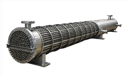
2.1 Shell‑and‑Tube Oil‑Heating Heat Exchanger (Most Commonly Used)
It includes fixed tube‑sheet, floating‑head and U‑tube types, featuring wide temperature‑and‑pressure adaptability and capability for high‑pressure service.
Main components: shell, tube sheets, tube bundle, baffles, channel covers and inlet/outlet nozzles.
Oil‑side flow‑path selection: For heavy fouling‑prone oils such as crude oil and residual oil, oil is normally arranged on the tube side to facilitate mechanical cleaning or pigging removal of internal oil scale. For light‑oil service or high‑pressure conditions, oil may flow on the shell side to reduce shell‑side pressure drop and mitigate leakage risks at high‑pressure sealing joints. Final selection shall be determined by comprehensive evaluation of pressure drop and sealing requirements.
Heating media (steam, thermal oil) generally flow on the shell side. It should be emphasized that where steam flows on the shell side, complete steam traps and non‑condensable gas vent connections must be provided to avoid condensate accumulation at the shell bottom or gas locking, which would drastically degrade heat‑transfer performance.
Floating‑head and U‑tube configurations are suitable for services with large thermal expansion. From practical engineering experience, structures with thermal compensation (floating‑head or U‑tube type) shall be prioritized when the temperature difference between heating‑medium inlet and oil outlet exceeds 80 ℃‑100 ℃, or when differential thermal expansion between tube bundle and shell exceeds allowable material limits; otherwise tube‑to‑sheet joints may crack under thermal stress. For small‑temperature‑difference conditions, cost‑effective fixed tube‑sheet designs may be adopted, optionally fitted with expansion joints.
Tube‑bundle materials include carbon steel and low‑alloy steel; stainless steel is selected for corrosive services. Equipment shall be manufactured in accordance with TEMA and ASME standards and comply with pressure‑vessel specifications.
2.2 Plate‑Type Oil Heater
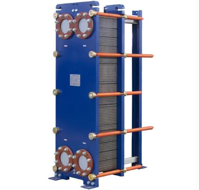
It delivers high heat‑transfer efficiency with compact footprint. Limited by gasket temperature resistance (generally ≤ 150 ℃) and pressure rating, it is mainly used for medium‑pressure, moderate‑temperature lubricating‑oil heating as well as low‑temperature heating / cooling steps in edible‑oil refining. It is not applicable for high‑viscosity, impurity‑laden heavy crude oil due to risk of flow‑passage blockage. Shell‑and‑tube exchangers remain the preferred option for edible‑oil heating above 200 ℃.
2.3 Coil‑Type Oil Heater
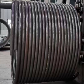
Typically immersed inside storage tanks, it heats tank‑stored oil to reduce viscosity and mitigate settling and solidification. It is widely used in heavy‑oil and crude‑oil storage tanks.
3. Key Design Considerations
Viscosity matching: Crude oil and heavy oil exhibit extremely high viscosity at low temperatures. Flow cross‑sections shall be properly sized to control oil‑side pressure drop and eliminate dead flow zones.
Anti‑coking and anti‑fouling design: Wall temperature shall be controlled to prevent local overheating and oil cracking. Access for inspection and cleaning shall be reserved. For heavy oils, tube‑side oil flow is preferred to support pigging and mechanical cleaning.
Thermal‑expansion compensation: Large temperature differences between oil and heating media create differential thermal elongation between shell and tube bundle. Floating‑head / U‑tube construction or expansion joints shall be adopted for large‑temperature‑difference services (inlet‑outlet temperature difference above 80 ℃‑100 ℃).
Material selection: Sulfur‑resistant materials shall be specified for sulfur‑containing crude oil; stainless steel shall be used for edible‑oil services to satisfy hygiene requirements.
4. Advantages and Disadvantages
| Advantages | Disadvantages |
|---|---|
| Indirect heating without direct flame contact eliminates local overheating and ensures high operational safety. | High‑viscosity oils deliver low heat‑transfer coefficients, requiring larger heat‑transfer areas. |
| Stable temperature control enables precise regulation of oil outlet temperature. | Crude‑oil and heavy‑oil services are susceptible to fouling, necessitating periodic chemical or mechanical cleaning. |
| Shell‑and‑tube units withstand high temperature and pressure, support long‑term continuous operation with mature maintenance procedures, and fit large‑scale industrial plants. | Plate‑type units impose strict requirements on medium cleanliness and operating temperature; they are unsuitable for heavily fouled oils and over‑temperature conditions. |
5. Typical Application Scenarios
- Petroleum refining: Crude‑oil preheating for distillation‑column feed; temperature elevation for transportation of heavy oil and residual oil.
- Oil‑gas gathering & transportation: Crude‑oil heating at wellheads and tank farms to lower viscosity for pipeline transportation and prevent blockage by solidified oil.
- Asphalt industry: Heating for asphalt storage tanks and asphalt production processes.
- Marine industry: Preheating fuel oil and heavy fuel oil to improve atomization and combustion performance.
- Food industry: Process heating for vegetable and animal oils. Plate‑type exchangers may be used for low‑temperature sections, while shell‑and‑tube types are recommended above 200 ℃.
- Energy & chemical industry: Temperature elevation for lubricating‑oil blending and waste‑oil regeneration systems.