


Bent boiler tubes are seamless or welded steel tubes that have been permanently formed into a curve — usually on a rotary draw bender or a hot-bending press — so they can carry steam, water, or flue gas along the actual geometry of a boiler. In a modern utility or industrial boiler, the tube path is rarely a straight line. Superheater, reheater, economizer, and water-wall circuits all have to snake around headers, buckstays, burners, and soot blowers. Instead of welding dozens of mitred elbows into the run, engineers specify a single tube bent to the required radius and angle. That is what bent boiler tubes deliver: a continuous pressure boundary with fewer welds, less pressure drop, and better fatigue behaviour under thermal cycling.
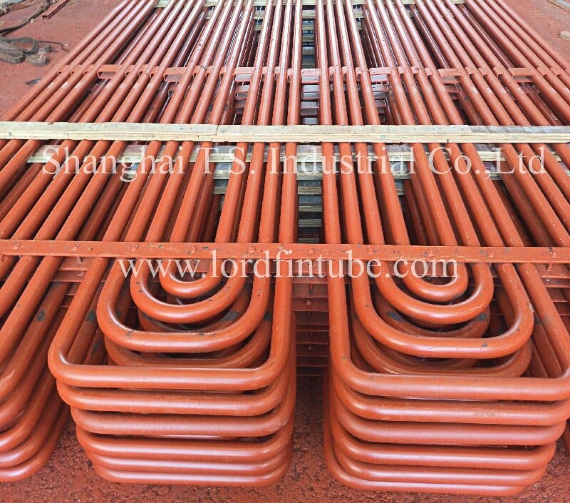
What Are Bent Boiler Tubes in Practical Terms?
A bent boiler tube is defined by three things: the parent tube, the bend geometry, and the heat-treatment or forming route used to produce the bend.
- Parent tube: a seamless or electric-resistance-welded steel tube, most often in carbon steel, Cr-Mo alloy steel, or austenitic stainless steel. Nominal outside diameter (OD) and wall thickness (WT) come from the boiler designers thermal-hydraulic calculation.
- Bend geometry: centreline bend radius (R), bend angle (θ), and the straight tangent lengths at each end. These are normally shown on a tube-bending drawing or a "spool drawing."
- Forming route: cold rotary draw bending, cold compression bending, or hot bending with induction or furnace heating, followed by any required post-bend heat treatment.
Bent boiler tubes are not fittings. A fitting is a separate cast or forged component welded between two straight pipe lengths. A bent tube is one continuous piece of tube with no circumferential weld at the bend. That difference matters for creep life, because circumferential welds in the high-temperature zone of a superheater are a common source of premature failure.
Core Parameters and Their Units
Four parameters drive almost every technical discussion about boiler tube bending. Each is defined below with its standard unit.
1. Bend Radius (R)
The bend radius is the radius of the tube centreline arc, measured in millimetres (mm) or expressed as a multiple of the outside diameter — for example 2D, 3D, or 5D, where D is the nominal OD. A "2D bend" on a 51 mm OD tube means a centreline radius of 102 mm. Bend radius controls how severe the strain is on the outer wall of the bend.
2. Bend Angle (θ)
The bend angle is the total angular deflection of the tube centreline, measured in degrees (°). Common values in boiler work range from 15° for a slight offset to 180° for a full U-bend in a pendant superheater. Angle and radius together determine the arc length of the bend.
3. Wall Thinning at the Outer Arc
When a tube bends, the outer wall stretches and thins while the inner wall thickens and may wrinkle. Wall thinning is expressed as a percentage (%) of the original nominal wall thickness. It is the single most important acceptance criterion for a bent boiler tube, because a thinned outer arc reduces the pressure-containing capability of the tube.
4. Ovality (Out-of-Roundness)
Ovality is the difference between the maximum and minimum outside diameter measured in the bend plane, expressed as a percentage (%) of the nominal OD. Excessive ovality flattens the bore, increases local pressure drop, and complicates orbital welding at the tube-to-header joint.
How to Calculate Bend Thinning, Ovality, and Arc Length
The three formulas below are the ones most often used on the shop floor and in the inspection report. They apply to both cold- and hot-formed bends.
Wall thinning rate
Wt = [(t0 − tb) / t0] × 100%
- Wt = wall thinning rate, %
- t0 = nominal wall thickness of the parent tube, mm
- tb = measured minimum wall thickness at the outer arc of the bend, mm
Ovality
Ov = [(Dmax − Dmin) / Dn] × 100%
- Ov = ovality, %
- Dmax = maximum measured OD in the bend plane, mm
- Dmin = minimum measured OD in the bend plane, mm
- Dn = nominal outside diameter, mm
Bend arc length
Lb = (π × R × θ) / 180
- Lb = developed length of the bend along the centreline, mm
- R = centreline bend radius, mm
- θ = bend angle, degrees
Developed length is used to calculate the cut length of the straight parent tube before bending. A practical minimum bend radius rule is R ≥ k × D, where k is a forming factor. For cold rotary draw bending of boiler tube, k typically falls between 1.5 and 3.0; tighter bends usually require hot forming, a mandrel, or both. The applicable k value must be confirmed with the tube manufacturer and the project specification, because it depends on material ductility, wall thickness ratio (t/D), and the bending equipment available.
Bent Boiler Tubes vs. U-Bend Heat Exchanger Tubes
Bent boiler tubes and U-bend heat exchanger tubes are both curved steel tubes, but they serve different pressure boundaries, follow different codes, and are inspected against different criteria. The table below sets out the main differences.
| Dimension | Bent boiler tubes | U-bend heat exchanger tubes |
|---|---|---|
| Primary application | Superheater, reheater, economizer, water wall in boilers | Shell and tube heat exchangers, condensers, feedwater heaters |
| Governing code | ASME BPVC Section I, ASME B31.1 | ASME BPVC Section VIII, TEMA |
| Typical tube OD | 25.4–114.3 mm | 6.35–50.8 mm |
| Typical bend radius | 1.5D–5D, often project-specific | 1.5D–3D, fixed by tube sheet layout |
| Bend angle | 15°–180°, multi-plane possible | Typically 180° (U-bend) in one plane |
| Tube-to-header / tubesheet joint | Welded or expanded into header | Rolled or expanded into tubesheet |
| Post-bend heat treatment | Often required for hot bending or thick walls | Stress relief may be required for some materials |
| Inspection focus | Wall thinning, ovality, NDT of bend | Eddy current, hydrostatic test, tube-to-tubesheet joint |
| Operating temperature | Up to ~650°C or higher depending on grade | Typically lower, application-specific |
| Corrosion environment | Steam side oxidation, fireside corrosion | Process fluid, cooling water, or steam |
| Best fit | High-temperature, high-pressure boiler circuits | Compact heat transfer bundles with removable tube bundles |
Design Trade-offs in Boiler Tube Bending
Bending is a compromise between flow performance, structural integrity, and manufacturability. The main trade-offs are described below.
Bend radius versus pressure drop and space
A larger radius gives a gentler bend, lower pressure drop, and less wall thinning, but it consumes more space in the boiler. A tighter radius saves space and shortens the tube run, but it increases strain on the outer arc and raises the risk of wrinkling on the inner arc. When the layout allows it, a 3D to 5D radius is a comfortable compromise for high-temperature superheater tubes.
Wall thinning versus parent wall thickness
Because the outer arc thins during bending, designers often start with a thicker parent wall so that the thinned section still meets the minimum calculated wall. This adds weight, cost, and thermal mass. Alternatively, the designer can specify a larger bend radius or a hot-forming route that reduces thinning. The choice is normally settled by comparing the calculated minimum wall at the bend against the code-required minimum.
Cold bending versus hot bending
Cold rotary draw bending gives good dimensional repeatability and a clean surface finish, and it suits carbon steel and many low-alloy grades at moderate radii. Hot bending becomes necessary for tight radii, heavy walls, and materials with limited room-temperature ductility, such as some high-chromium martensitic grades. Hot bending requires temperature control and often a post-bend heat treatment to restore the microstructure.
Bend angle versus number of bends per tube
Multiple bends in one tube reduce the total weld count but increase the complexity of the bending sequence and the risk of cumulative dimensional error. Tubes with three or more bends in different planes generally need a bending fixture and a first-article dimensional report before series production.
Technical Parameter Table
| Parameter | Unit | Typical range | Notes |
|---|---|---|---|
| Outside diameter (OD) | mm | 25.4 – 114.3 | Confirm against the boiler design drawing |
| Wall thickness (WT) | mm | 2.6 – 12.7 | Wall at the bend must satisfy the minimum calculated wall |
| Bend radius | mm or ×D | 1.5D – 5D | Tighter radii may require hot forming |
| Bend angle | ° | 15 – 180 | U-bends at 180° are common in pendant superheaters |
| Wall thinning at outer arc | % | ≤ 10 – 12.5 | Acceptance limit from project specification |
| Ovality in bend plane | % | ≤ 5 – 8 | Measured with a micrometer or laser gauge |
| Inner arc wrinkle height | mm | Project-specific | Normally limited by the purchasers specification |
| Straight tangent length | mm | Per drawing | Must leave enough length for orbital welding |
| Tube length | m | Up to 12 or as required | Limited by transport and handling |
| Surface finish | — | Free of cracks, laps, and scale | Visual plus NDT verification |
Materials and Standards
Material selection for bent boiler tubes follows the operating temperature and the corrosion environment of the specific boiler circuit.
| Material group | Typical grades | Typical service | Applicable standard |
|---|---|---|---|
| Carbon steel | SA-210 A1, SA-210 C | Water wall, economizer, low-temperature superheater | ASME SA-210 |
| Cr-Mo alloy steel | SA-213 T11, T22 | Superheater and reheater, moderate metal temperature | ASME SA-213 |
| High-chromium martensitic | SA-213 T91, T92 | High-temperature superheater and reheater | ASME SA-213 |
| Austenitic stainless | SA-213 TP304H, TP347H, Super304H | Final-stage superheater, high steam oxidation | ASME SA-213 |
Bending and post-bend treatment are governed by the purchasers specification and the applicable construction code. Where a standard is not stated on the enquiry, the bend shall be produced according to project specification, with the applicable standard to be confirmed before production. Typical referenced documents include ASME Boiler and Pressure Vessel Code Section I, ASME B31.1, and the purchasers own bending procedure specification.
Where Bent Boiler Tubes Are Used
- Utility boilers: pendant and platen superheaters, reheater panels, and economizer banks where tubes must follow a curved gas path.
- Industrial and biomass boilers: water walls, screen tubes, and convection banks in confined layouts.
- HRSG units: superheater and reheater modules in combined-cycle plants.
- Waste heat recovery: heat exchanger tube bundles in cement, steel, and glass plants.
- Replacement spools: single bent tubes or bent-and-welded assemblies for boiler outages and life-extension projects.
- Power plant EPC and maintenance contractors: prefabricated tube spools delivered ready for erection.
Selection Factors When Specifying Bent Boiler Tubes
- Operating metal temperature. This sets the material group and the allowable stress used to calculate minimum wall thickness.
- Design pressure and calculated minimum wall. The wall at the outer arc of the bend must remain above the code minimum after thinning.
- Bend geometry. Radius, angle, plane changes, and tangent lengths determine whether cold or hot forming is required.
- Forming route and heat treatment. Confirm whether post-bend normalising, stress relief, or solution annealing is required for the chosen grade.
- Inspection requirements. Agree on NDT methods, sampling frequency, and whether a first-article dimensional report is required.
- End preparation. Specify bevel geometry, bore alignment, and whether caps are needed for transport.
- Traceability. Heat number, material certificate, and bending record must be linked to each tube or bundle.
Quality Control and Testing
| Test item | Purpose | Typical method |
|---|---|---|
| Material verification | Confirm grade and chemistry | Mill certificate, PMI, spectrometric analysis |
| Dimensional check | Verify OD, WT, radius, angle, tangents | Micrometer, calliper, template, CMM |
| Wall thickness at bend | Confirm thinning is within limit | Ultrasonic thickness gauge, sectioning on samples |
| Ovality measurement | Confirm bore roundness | Micrometer in the bend plane |
| Surface inspection | Detect cracks, laps, wrinkles | Visual, magnetic particle, dye penetrant |
| Volumetric examination | Detect internal defects | Ultrasonic testing, eddy current testing |
| Hydrostatic test | Verify pressure integrity | Hydrostatic test per project requirement |
| Hardness check | Verify post-bend heat treatment | Portable hardness tester |
| Metallographic examination | Confirm microstructure after hot bending | Laboratory replica or sample section |
Packing and Shipping
- End protection: plastic or steel caps on both tube ends to protect bevels and bores.
- Surface protection: rust-preventive oil or VCI film for carbon and low-alloy tubes; interleaving for stainless grades to avoid carbon contamination.
- Bundling: tubes bundled with steel strapping and wooden or plastic spacers so that bends are not loaded against each other.
- Fixtures for large bends: bent spools that cannot self-support are shipped in wooden cradles or steel frames.
- Marking: bundle tag showing heat number, drawing number, quantity, and project reference.
- Documentation: material certificates, dimensional report, and NDT reports packed with the shipping documents.
- Transport: sea freight in containers or break-bulk, depending on tube length and bend envelope. Lifting points must be marked to prevent point loading on the bends.
FAQ
What are bent boiler tubes?
Bent boiler tubes are steel tubes permanently formed into a curve so they can follow the actual layout of a boiler circuit. They are used in superheaters, reheaters, economizers, and water walls, and they replace welded elbow assemblies with one continuous pressure boundary.
How are bent boiler tubes manufactured?
The parent tube is cut to a developed length, then formed on a rotary draw bender, a compression bender, or a hot-bending press. After forming, the tube is dimensionally checked, inspected for wall thinning and ovality, and given any post-bend heat treatment required by the material and specification.
What is an acceptable wall thinning limit for a bent boiler tube?
Typical acceptance limits are around 10% to 12.5% maximum thinning at the outer arc, but this is a typical range only. The governing limit must come from the project specification and the design engineer, and it must be checked against the code-required minimum wall thickness.
What is the minimum bend radius for a boiler tube?
A practical minimum is often expressed as R ≥ k × D. For cold rotary draw bending, k typically falls between 1.5 and 3.0. Tighter radii usually require hot forming or a mandrel. The final value depends on material ductility, wall thickness ratio, and the bending equipment, and must be confirmed with the manufacturer.
Why use a bent tube instead of a welded elbow?
A bent tube removes the circumferential welds at the bend. That lowers pressure drop, reduces the number of weld heat-affected zones in the hot region, shortens erection time, and improves fatigue behaviour under thermal cycling.
Which materials are used for bent boiler tubes?
Common grades include carbon steel such as SA-210 A1 and C, Cr-Mo alloys such as SA-213 T11 and T22, high-chromium grades such as T91 and T92, and austenitic stainless grades such as TP304H and TP347H. The choice follows the operating metal temperature and the corrosion environment.
How are bent boiler tubes inspected?
Inspection typically covers material verification, dimensional checks, ultrasonic wall thickness measurement at the bend, ovality measurement, surface examination, volumetric NDT, and a hydrostatic test where required. The exact scope is set by the project specification.
Need bent boiler tubes matched to your drawing? Send the tube size, material grade, bend radius, angle, and quantity, and our engineering team will review the forming route and inspection plan.
Request a Quote